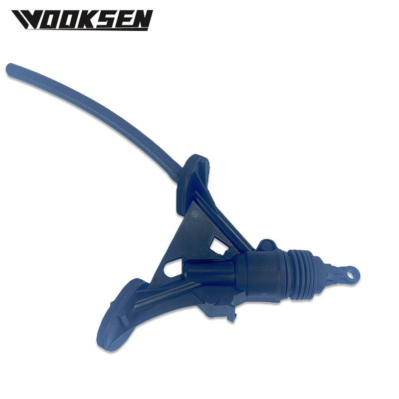
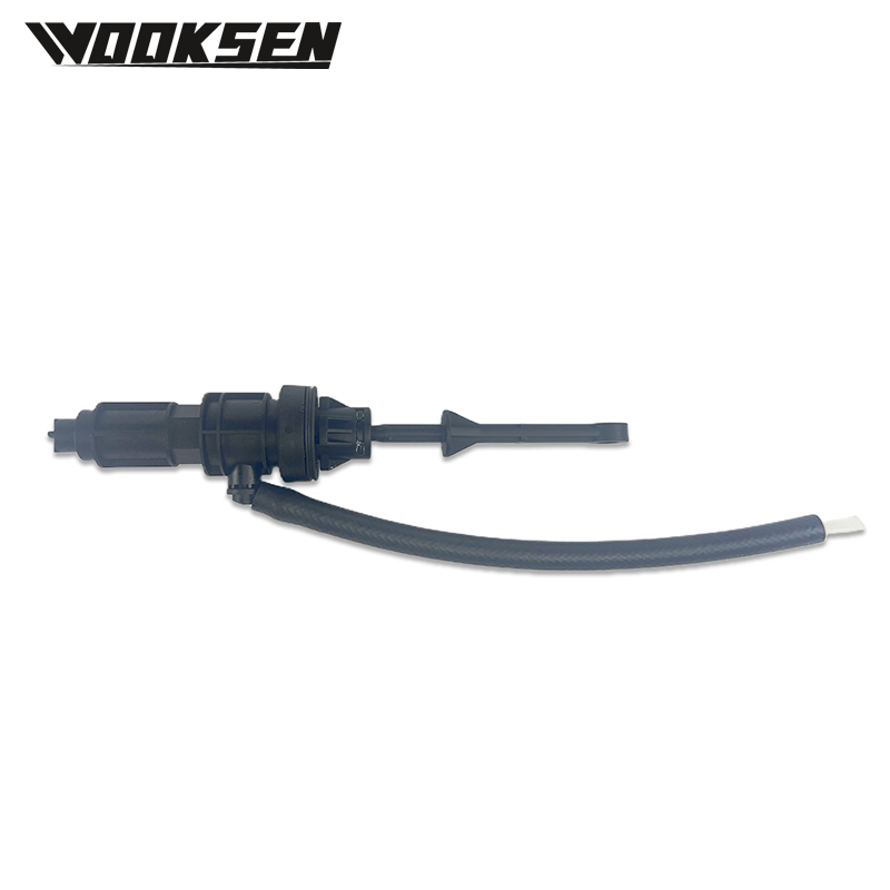
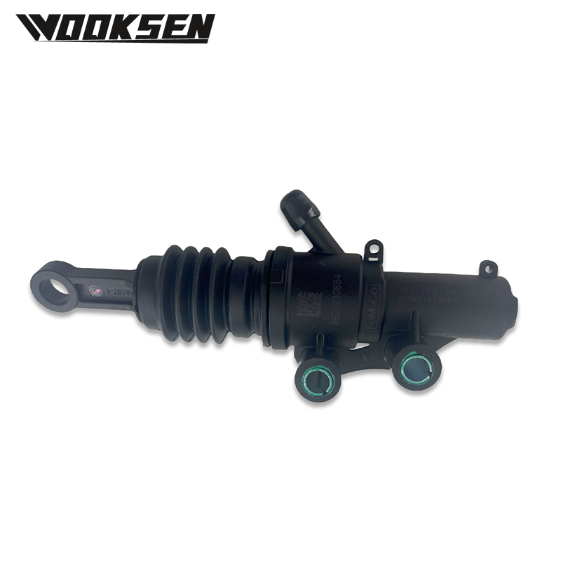
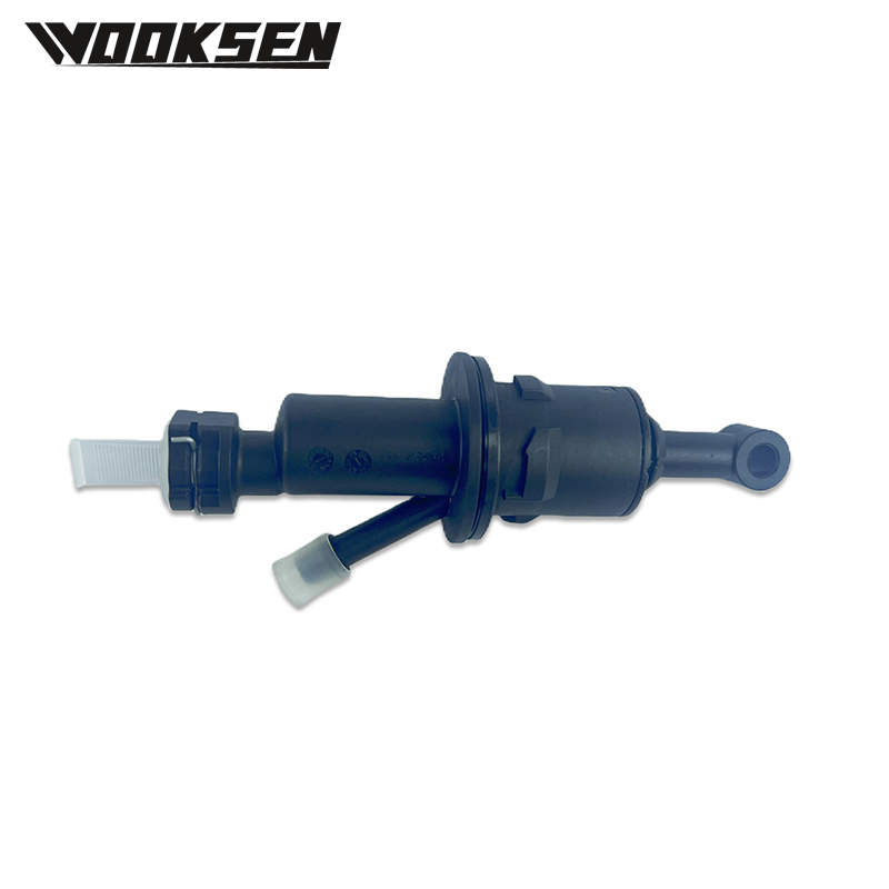
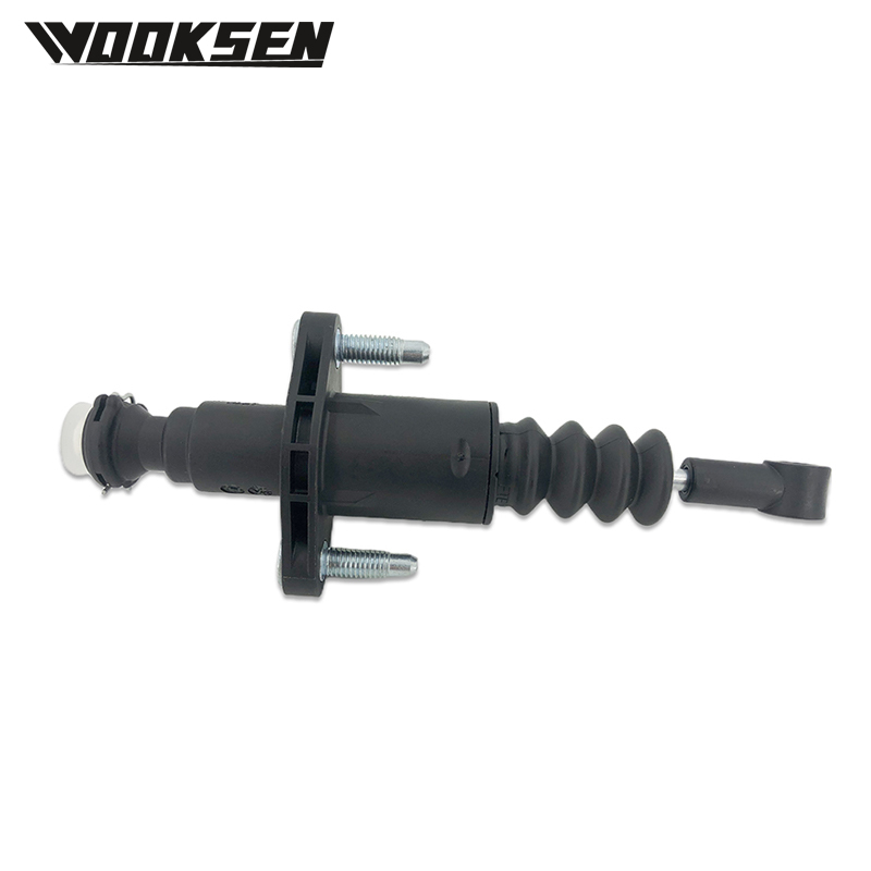
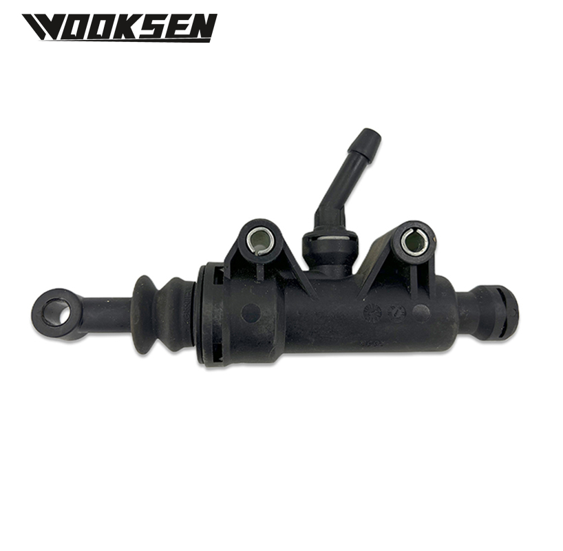
A0044302801 Brake assembly units form a critical part of the braking system on commercial and industrial vehicles. These assemblies convert kinetic energy into controlled stopping force through friction and mechanical advantage. Buyers responsible for fleet parts or vehicle production lines examine construction details, material choices, and functional behavior when sourcing this type of component.
Core structure of A0044302801 Brake assembly
The A0044302801 Brake assembly typically includes a backing plate or caliper body, friction elements, actuating hardware, and return mechanisms. In drum-style configurations the shoes expand against a rotating drum; in disc-style versions pads clamp against a rotor. Mounting points are machined to align with the axle or knuckle so that force is transmitted evenly.
Internal clearances and spring tensions are set so that the assembly returns to a non-contact position after each application. Seals and boots protect moving parts from dust and moisture while allowing free movement of the actuating components. This basic architecture supports repeatable braking performance under varying load conditions.
Production techniques for A0044302801 Brake assembly
Manufacturing begins with casting or forging of the main structural parts. These blanks are then machined to create precise mounting faces, pivot points, and friction-surface interfaces. Friction materials are bonded or riveted to shoes or pad backings under controlled pressure and temperature.
Actuating levers, rollers, and springs are formed and heat-treated for durability. Final assembly joins all components on fixtures that maintain correct geometry and preload. Each completed unit is checked for free movement and dimensional accuracy before it leaves the production area. Process controls focus on consistency of friction attachment and mechanical fit.
Key functional characteristics
An A0044302801 Brake assembly must generate sufficient friction force while managing the heat produced during repeated stops. The friction surfaces are formulated to maintain stable coefficient values across a practical temperature range. Mechanical advantage within the assembly multiplies the input force from the hydraulic or pneumatic actuator.
Return springs and adjusters keep running clearances within design limits so that drag remains low during normal travel. The overall package is designed to fit within the space constraints of the wheel end while providing access for inspection. These functional traits support controlled deceleration across the vehicle’s operating envelope.
Matching A0044302801 Brake assembly to vehicle needs
Buyers review axle type, actuator style, and vehicle gross weight when selecting an A0044302801 Brake assembly. Available space at the wheel end and existing drum or rotor dimensions further refine the choice. Expected duty cycle—highway, urban, or mixed—influences friction formulation and hardware durability requirements.
Clear definition of these operating conditions allows the supplier to confirm compatibility and recommend the appropriate configuration. Matching the assembly to the actual application early supports proper integration and stable braking performance once the vehicle enters service.
Technical factors in selection
Mounting bolt patterns, actuator lever ratios, and adjuster mechanisms must align with the rest of the brake system. Clearance to the wheel and suspension components affects both installation and heat dissipation. Friction material characteristics need to suit the typical operating temperatures of the vehicle’s routes and loads.
Understanding the complete wheel-end layout—including drums or rotors, sensors, and dust shields—helps ensure the selected A0044302801 Brake assembly functions as part of an integrated system. These technical points turn a general replacement or production part into a reliable element of the vehicle’s braking architecture.

 English
 русский
 Español
 عربى