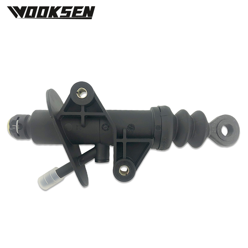
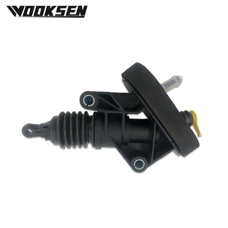
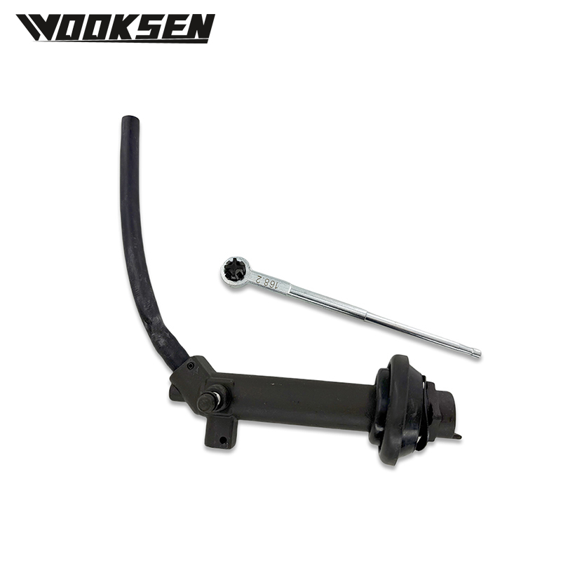
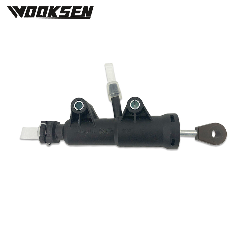
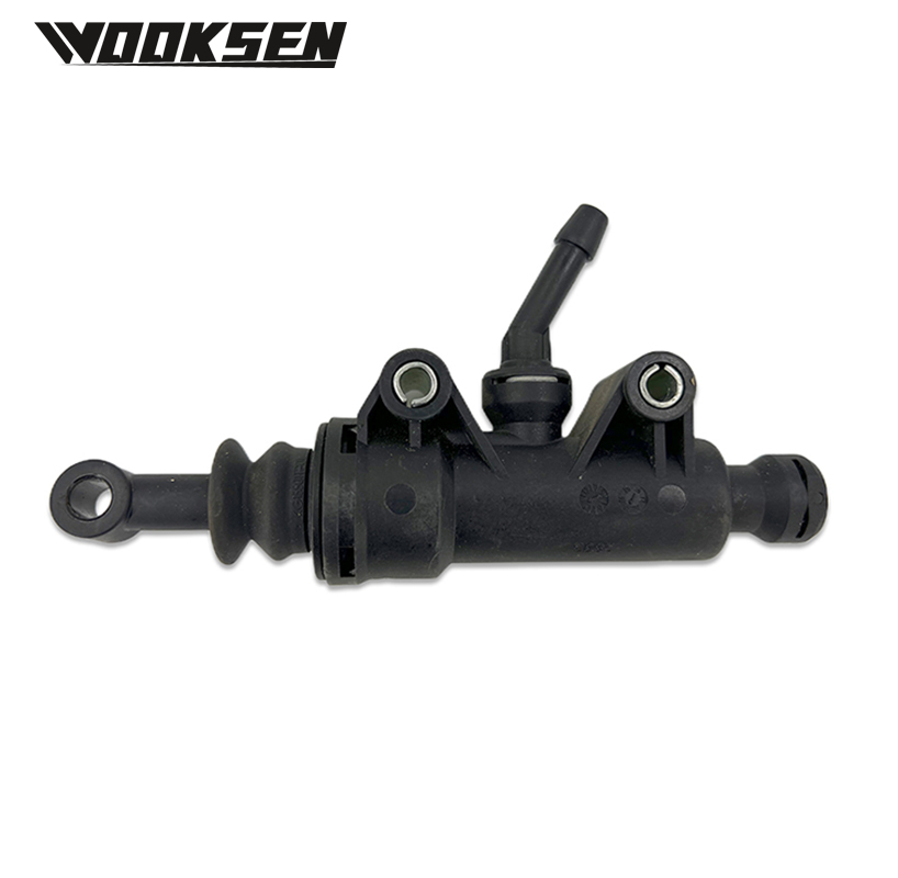
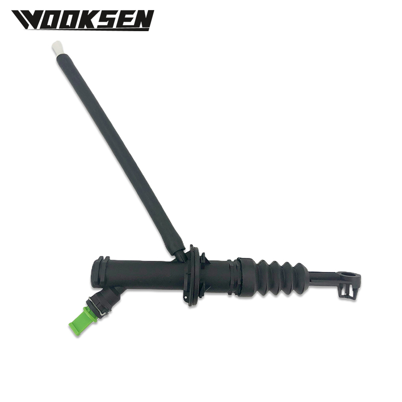
The C2S14144 Clutch assembly plays a clear role in connecting and disconnecting power flow between an engine and a transmission. Drivers and technicians often notice smoother shifts once this unit is in place, yet few stop to examine its internal layout. This piece walks through the main parts, the way they interact, and the everyday settings where the unit appears.
Main Parts Inside the Unit
A typical clutch pack starts with a pressure plate, a friction disc, and a release bearing. In the C2S14144 Clutch assembly these elements sit in a compact housing that keeps alignment tight. The pressure plate presses the disc against the flywheel when the pedal is free. When the driver presses the pedal, the release bearing pulls the pressure plate back, letting the disc spin freely.
Springs inside the pressure plate spread the load evenly so the disc does not warp under heat. The friction material on the disc is chosen for steady grip without sudden grab. Together these pieces form a reliable path for torque. The C2S14144 Clutch assembly keeps each surface parallel so contact remains consistent across the full face of the disc.
How Power Moves Through the System
Torque travels from the crankshaft to the flywheel. When the clutch is engaged, the disc locks to the flywheel and turns the input shaft of the transmission. Disengaging the C2S14144 Clutch assembly breaks that lock, allowing gear changes without grinding.
Hydraulic or cable linkages convert pedal movement into the small motion needed at the release bearing. The design of the C2S14144 Clutch assembly limits free play so the driver feels a firm, predictable take-up point. Once the pedal rises, the springs reapply pressure and the disc locks again. This cycle repeats thousands of times during normal driving without sudden slip or chatter when the unit is correctly adjusted.
Common Vehicle Applications
Light trucks, passenger cars, and certain light commercial machines all use similar clutch layouts. The C2S14144 Clutch assembly fits engines that produce moderate torque levels and need a compact package. Installers often mount it on transverse or longitudinal powertrains depending on the chassis layout.
In daily use the unit handles stop-and-go traffic as well as steady highway speeds. Because the friction surface is sized for the expected load, heat builds gradually and then dissipates through the flywheel and housing. The C2S14144 Clutch assembly therefore stays within normal operating temperatures under ordinary loads.
Design Details That Matter
Housing thickness, spline count on the disc hub, and the angle of the diaphragm spring all influence feel and durability. Engineers select these dimensions so the pedal effort stays reasonable while still delivering enough clamp force. The C2S14144 Clutch assembly balances these factors without relying on oversized parts.
Alignment pins or dowels keep the pressure plate centered on the flywheel. This simple feature reduces vibration that could otherwise travel into the cabin. The overall package remains light enough that it does not add unnecessary mass to the rotating assembly.
Practical Observations from the Field
Technicians who install or inspect the unit note that correct flywheel surface finish and proper torque on the bolts are essential for smooth engagement. Once those steps are complete, the C2S14144 Clutch assembly settles into a consistent bite point. Drivers report that shifts feel clean and that the pedal returns with a natural spring rate.
The same unit appears across several vehicle platforms that share similar engine and transmission combinations. This commonality simplifies parts stocking for workshops that service multiple models. Because the core geometry stays the same, training for replacement stays straightforward.

 English
 русский
 Español
 عربى
عربى